Case Study:
Aircraft Cooling System Design
Client:
Northrop Grumman
Project Scope:
Cooling Design, Acoustic Testing, Prototyping
Methods:
Design & Testing, CAD, Parts Procurement
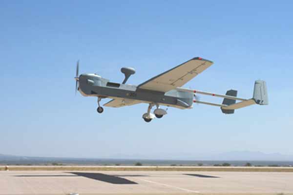
Northrop Grumman was contracted by the military to modify Hunter unmanned aerial vehicles (UAVs) from gasoline engines to turbo charged diesel engines. The plane needed new cowling to accommodate radiators and an intercooler. Flometrics support included:
Design new cowlings and cooling paths
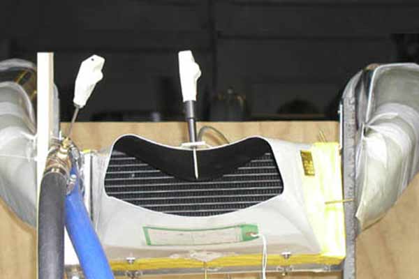
Construct and test full size mock up of the cooling system
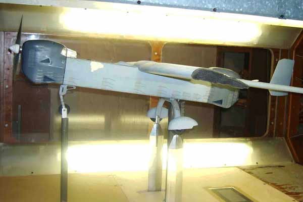
Modify wind tunnel model and conduct wind tunnel measurements
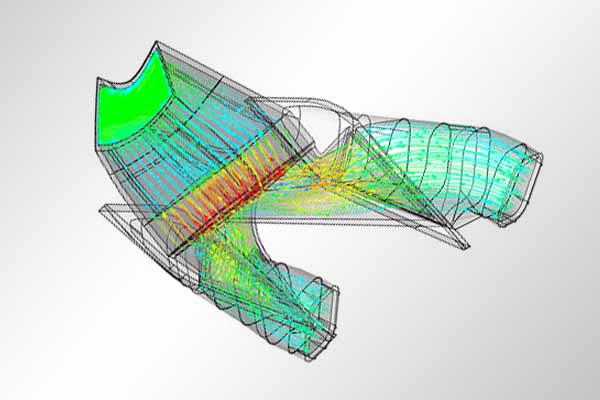
CFD of the UAV and cooling passages
Write computer software to model flight parameters of the vehicle
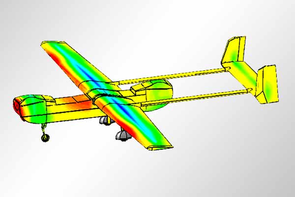
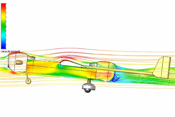
The first step in the design process was to calculate the pressure coefficient over the entire aircraft in order to determine the best location for cooling air inlets and outlets. The flow through the scoops and ductwork was modeled in CFD to assure free flow of the cooling air.
The top right image shows the pressure coefficients on the original aircraft based on computational fluid dynamics (CFD) calculations, without propellers. The resulting information was used to select locations for the various cooling inlets and outlets. Then the intercoolers and radiators were tested with realistic flows, temperatures and pressures in a laboratory environment. This bench testing resulted in minor modifications which resulted in optimal performance of the system.
A scale model of the modified aircraft was fitted with prototype scoops, ducts, radiator and intercooler models and was tested in the wind tunnel with motorized propellers. The aircraft was then underwent extensive testing and later was placed in service with the U.S. military.